The Ammeter vs. Voltmeter Secret: Why Internal Resistance is the Key to the ‘Series vs. Parallel’ Rule
I’m Ken Kuwako, Science Trainer. Every Day is an Experiment.
You probably learned in middle school science that “ammeters must be connected in series, and voltmeters must be connected in parallel.” You may have simply memorized it as “the rule,” but why must it be done that way? Ammeters and voltmeters look nearly identical. Perhaps you even thought, “Is the only difference the color of the terminals?”In fact, while the internal mechanisms of the two are similar, they have one major, crucial difference. And this “rule of connection” is based on a profound reason. In the world of high school physics, you learn the secret key to this difference: “Internal Resistance.” Today, I will introduce the concept of internal resistance and a simple experiment to prove it. Let’s see if what you learned in the textbook is actually true with your own eyes!
The Ammeter’s Secret: A Small Resistance that Doesn’t “Block” the Flow
An ammeter is a tool designed to measure the “amount (or intensity) of electric current” flowing through a circuit. Imagine installing a “flow meter” mid-way through a water pipe to measure the volume of water passing through.If the flow meter itself becomes an “obstacle” that impedes the water flow, you won’t be able to measure the correct amount, right? The same applies to an ammeter. It is inserted into the circuit, interrupting the current’s path (in series). Therefore, to ensure it doesn’t interfere with the current that was originally flowing in the circuit, the ammeter’s own resistance (internal resistance) is built to be as small as possible.
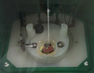
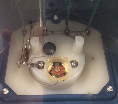
Inside the ammeter (viewed from the back)
【Key Takeaway】Ammeters must be connected in series, with an internal resistance that is virtually zero (very small)!
What happens when you change the maximum measurable current (e.g., $50 \text{ mA}$ or $5 \text{ A}$)? It turns out that the internal resistance becomes even smaller the higher the current range you select (like $5 \text{ A}$). This is because there is a mechanism to divert the majority of the current through a separate path (a bypass) so that the delicate meter (the part that moves the needle) doesn’t get damaged. This bypass resistance is called a “shunt resistor” and is connected in parallel to the meter. As a result, the total resistance of the entire instrument is made even smaller.
The Voltmeter’s Secret: A Large Resistance that Doesn’t “Steal” the Flow
A voltmeter, on the other hand, is a tool to measure the “difference in voltage (difference in electrical pressure)” across two points in a circuit. Imagine measuring the “difference in water pressure” between two points in a pipe.To measure the water pressure, you connect a pressure gauge by drilling a hole in the pipe. But if water gushes out through that connection, the original water pressure will change, right?The same is true for a voltmeter. It is connected across the two points you want to measure (in parallel). Therefore, to prevent the original circuit’s current from flowing into the voltmeter, the voltmeter’s own resistance (internal resistance) is built to be as large as possible.
Inside the voltmeter (viewed from the back)
【Key Takeaway】Voltmeters must be connected in parallel, with an internal resistance that is effectively infinite (very large)!
What happens when you change the maximum measurable voltage (e.g., $3 \text{ V}$ or $300 \text{ V}$)? It turns out that the internal resistance becomes even larger the higher the voltage range you select (like $300 \text{ V}$). This is because the meter inside the voltmeter can be destroyed if the voltage exceeds its limit. Therefore, there is a mechanism where a separate resistor takes on the excess voltage. This voltage-sharing resistor is called a “multiplier resistor” and is connected in series with the meter. As a result, the total resistance of the entire instrument is made even larger.
Is the Theory True? Let’s Test “Internal Resistance” with a Multimeter!
This is what we learn in class, but it’s essential to actually confirm the internal resistance, right? Today, I will introduce a simple experiment to do just that. Let’s take a multimeter (circuit tester) to the school lab and measure it!
Science Recipe: Peeking Inside the Ammeter and Voltmeter
Materials Needed: Ammeter, Voltmeter, Multimeter (Digital Multimeter, etc.)
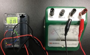
1: Measure the Resistance of the Ammeter’s Terminals with the Multimeter
(*Use the multimeter’s “Resistance ($\Omega$)” mode. Touch the red and black probes of the multimeter to the ammeter or voltmeter terminals.)When connected to the terminal for measuring up to $50 \text{ mA}$ (milliamperes), the display showed $0.19$ ohms ($\Omega$). That’s very small!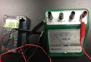 When connected to the terminal for measuring up to $5 \text{ A}$ (amperes), the display showed $0.05$ ohms ($\Omega$). The terminal for measuring a larger current ($5 \text{ A}$) has an even smaller internal resistance!
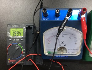
2: Measure the Resistance of the Voltmeter’s Terminals with the Multimeter
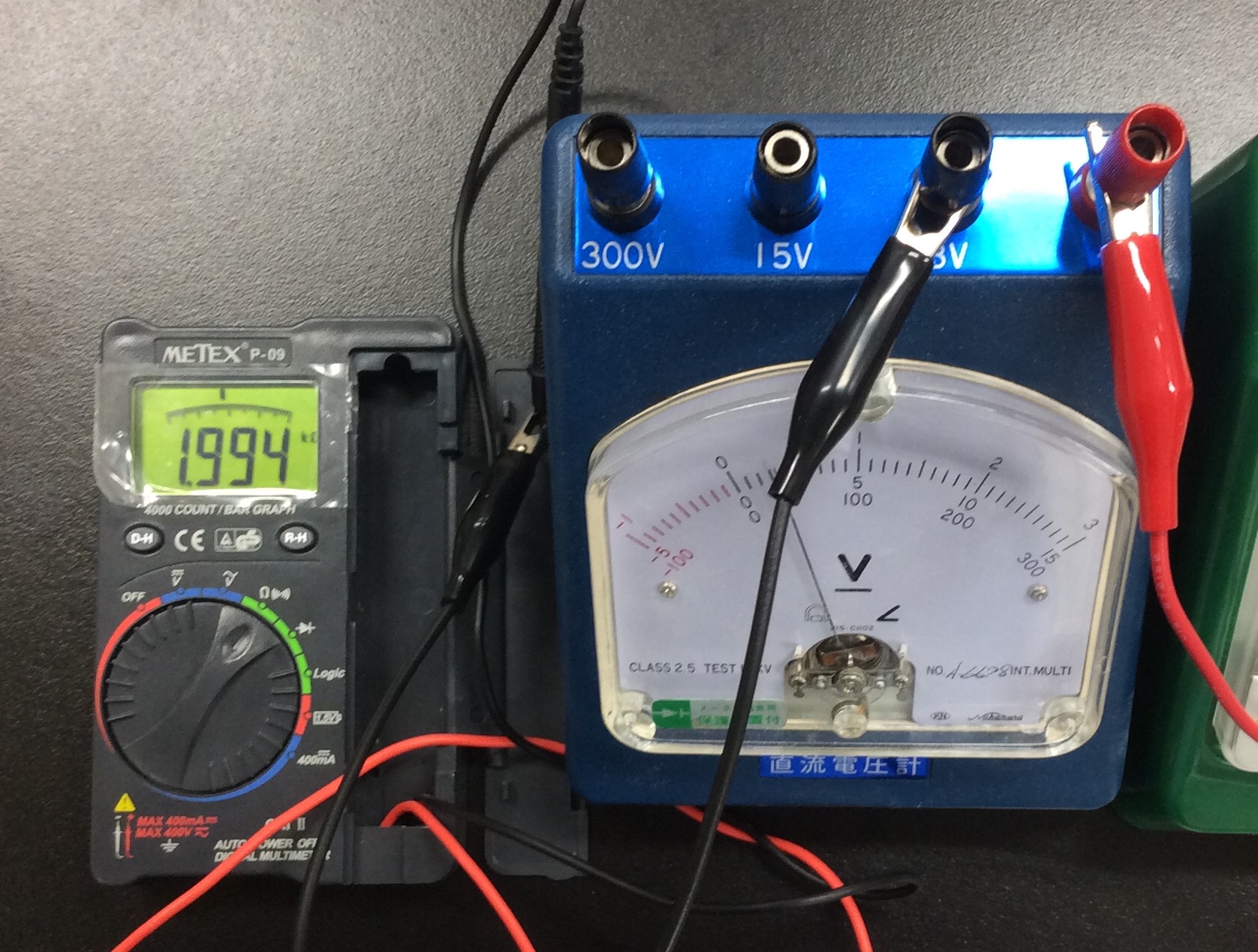
Measuring at the $3 \text{ V}$ (volt) terminal showed $1.994 \text{ k}$ ohms ($\text{k}\Omega$) which equals $1994$ ohms ($\Omega$). ($k$ stands for $1000$ times.) The resistance is incredibly high compared to the ammeter! Next, let’s connect to the $300 \text{ V}$ terminal.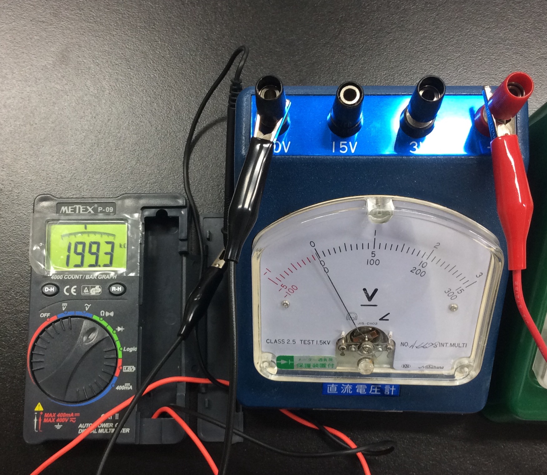 This displayed $199.3 \text{ k}$ ohms ($\text{k}\Omega$) which equals $199,300$ ohms ($\Omega$). The terminal for measuring a larger voltage ($300 \text{ V}$) has an even larger internal resistance!
Science is More Interesting When You Know “Why”!
As shown, we can actually confirm that the internal resistance is completely different for voltmeters and ammeters, and that the resistance value changes depending on the maximum range terminal used. Even the things we memorized as “rules” in middle school science have a clear reason behind them. Asking “Why?” is the doorway to the fun and fascinating world of science!Many ammeters and voltmeters have a transparent back, allowing you to see inside. I encourage you to take a look! Check where the resistors (shunts and multipliers) are connected $(\hat{}_ \wedge)$. You should be able to see the ingenuity of the person who designed it!
Inquiries and Requests
Bring the wonder and fun of science closer to you! I put together easy-to-understand fun science experiments you can do at home and the tricks behind them. Feel free to search for more!・The content of “Kuwako’s Science Notes” is now a book. Find out more here・About the operator, Ken Kuwako: here・For various requests (writing, lectures, experiment classes, TV supervision/appearances, etc.): here・Article updates are posted on X!
![]() We stream experiment videos on Kuwako’s Science Channel!
We stream experiment videos on Kuwako’s Science Channel!
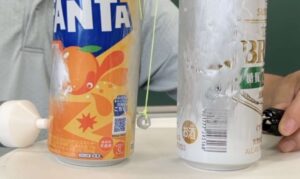
6月のイチオシ実験!
レモンやオレンジで風船を割ろう!インパクトが抜群のリモネン風船の実験
テレビ番組監修・イベント等のお知らせ
- 6月3日(水)20:30〜 「
バカリズムのちょっとバカりハカってみた!」(テレビ東京)を科学監修・出演します。テーマは「 そばの出前は何人前まで運べるのか、限界を測ってみた」です。 - 6月4日(木) 7:00〜 「THE突破ファイル」(日本テレビ)について科学監修しました。
- 6月14日(日) 千葉大学インスタレーション「探究」にて講師を務めます
- 6月26日(金) 公開研究会「脱作業化!デジタル化と段階的指導で実現する オームの法則の探究」
- 6月28日(日) ダビンチマスターズ@昭和女子
- 7月18日(土) 教員向け実験講習会「ナリカカサイエンスアカデミー」の講師をします。お会いしましょう。
書籍のお知らせ
- 『大人のための高校物理復習帳』(講談社)…一般向けに日常の物理について公式を元に紐解きました。特設サイトでは実験を多数紹介しています。※増刷がかかり6刷となりました(2026/02/01)

- 『きめる!共通テスト 物理基礎 改訂版』(学研)… 高校物理の参考書です。イラストを多くしてイメージが持てるように描きました。授業についていけない、物理が苦手、そんな生徒におすすめです。特設サイトはこちら。

各種SNS(更新情報をお届け!)
X(Twitter)/instagram/Facebook(日本語)
Explore
- 楽しい実験…お子さんと一緒に夢中になれるイチオシの科学実験を多数紹介しています。また、高校物理の理解を深めるための動画教材も用意しました。
- 理科の教材… 理科教師をバックアップ!授業の質を高め、準備を効率化するための選りすぐりの教材を紹介しています。
- Youtube…科学実験等の動画を配信しています。
- 科学ラジオ …科学トピックをほぼ毎日配信中!AI技術を駆使して作成した「耳で楽しむ科学」をお届けします。
- 講演 …全国各地で実験講習会・サイエンスショー等を行っています。
- About …「科学のネタ帳」のコンセプトや、運営者である桑子研のプロフィール・想いをまとめています。
- お問い合わせ …実験教室のご依頼、執筆・講演の相談、科学監修等はこちらのフォームからお寄せください。